Motivation
I’ve always been a fan of thin clients. About 3-4 years ago, I was blown away by the countless low-cost devices becoming available on the market. Devices like the Raspberry Pi Zero for $5. At that point, the idea of a portable low-cost low-power Linux terminal came to mind. Having loved e-paper technology when it first came out, I thought it’d be a perfect use for this kind of device.
The Components
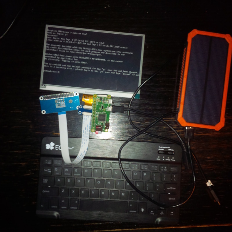
So, I went looking around for a solution. I settled on the Waveshare 7.5" E-Ink display. Together with the display ($55), a Raspberry Pi Zero W ($10), a Bluetooth keyboard ($20), and a solar powered battery ($30), I was hoping to make a cheap (< $150), easy to replace Linux terminal that I’d always provide access to my servers. I could command an army of super-computers from this humble low-power terminal.
Sadly, the parts sat on my shelves for years and I’ve only just found the time to try out the project. Lately, due to some other projects, I’ve been getting away from cryptocurrencies and back to embedded systems. So this was the perfect time to tackle it.
The Build and Background
First, the easy stuff. The Raspberry Pi Zero can be powered by one of its two micro USB ports. This removes the need for an additional buck or boost converter. Simply plug the battery pack into the Pi. The Pi uses roughly 150mA while in use and the battery pack provide 30,000mAh of power. That’s over a week of continuous use. If you add in whatever (small) power the solar panel provides, we should have plenty, if not an endless supply of power. I dunno know about you but that sounds pretty awesome to me. Always connecteddddddddd. Next, the keyboard is just Bluetooth, so we just pair that to get a keyboard.
Finally, the less easy stuff. The e-ink display connects over an SPI bus. In short, this is a four or three wire serial bus that’s popular in embedded systems. The Pi has an SPI controller over GPIO pins and Linux supports it. No problems there.
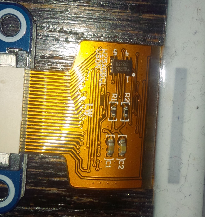
Physically, the e-ink display comes with a "HAT" driver board that converts the 3.3V supply to the higher voltages required for the screen. The HAT just plugs directly into the GPIO header of the RPi. At this point, I wanted to know which connections are actually being used. Looking at the pinout of the HAT, we’ve got VCC, GND, DIN, CLK, CS, DC, RST, and BUSY.
It’s here where I wanted to dig into the details of technologies. You could probably get away with not knowing much about how SPI or e-ink work, but that’s not the kind of person I am. I’m a very… curious man. So I dug into the provided HAT schematic, and the details of how SPI and e-ink work. I won’t go into the details of the latter since others have done both well enough. There are even lots of a good YouTube video of how both of SPI and e-ink work. In particular, the video on the e-ink uses a 4.2" version that I’ll refer to later on.
After doing that research, I was able to conclude that pins on the HAT were for the power supply, ground, SPI data in (MOSI), SPI clock, SPI cable select. It’s worth noting that there’s no SPI data out (MISO). This was strange at first but after examining the datasheet for the e-ink display, it became clear that reading from the device was unnecessary. The remainder of the signals were determined by staring at the HAT schematic for a bit longer. They turned out to be data/command select, reset, and a busy signal. I’ll explain these more later on.
The Scope
Having some background, the first real question was whether to use the Linux Frame Buffer (FB) or the Direct Rendering Manager (DRM) subsystem to connect into the device. The former is simple and doesn’t require CPU-intensive application like Xorg to use. The latter is more modern and versatile. I settled on the FB given the small scope of the project, ease of use, direct nature of the solution, and the fact that I’ve been moving back to text-based applications for many things I do. Plus, there is an FB driver for Xorg anyway. And given the slow refresh rate of e-ink displays themselves, performance will never really be neck-breaking fast.
Okay so great, we need a driver that’ll connect the Linux FB with the SPI bus. There’s no GPU or anything fancy like that. The driver just needs to take the FB image buffers and spit them out onto the SPI bus in a format the device requires.
With some quick searching, I found a Linux kernel FB driver for Waveshare e-ink devices. Could this project really be this easy? As usual, things are rarely this easy. Turns out there are a lot of different controllers for these Waveshare displays that all are just a little different. So my initial hope of being able to use the existing drivers went from "just integrate into kernel build process", to "just need to change up the commands", to "need to rewrite the whole thing". Ah well, at least it provided a good example.
The Solution
So let’s look into the details of the driver I wrote. As with most Linux drivers, higher-level details tend to be towards the bottom of the file. So first things first, at the bottom of the driver, it registers with Linux using a call to module_spi_driver. This registers the code as any normal Linux driver would (ie. module_init), as well as with the SPI subsystem. As the system boots, something will detect the physical device and match it with the driver.
Device Detection
Depending on the platform, there are a few ways devices are typically discovered in Linux. For PCs, this is usually with ACPI. For embedded systems, because of the cost of ACPI, a simpler approach is usually taken with board files or device trees (DTs). The former is deprecated in favour of the latter. Board files are essentially just drivers that add the device to the system. Device information provided by the board file is then matched with a driver. With device trees, the Open Firmware (OF) framework registers the device and matches it against a supplied of_match_table in the driver. This of_match_table is matched against the compatibility property on a device tree node.
For the our wseinkfb driver, the device tree entry is
wseinkfb@0 {
        compatible = "waveshare,75";
        ...
}
which is matched against the driver OF table
static const struct of_device_id ws_eink_of_match[] = {
  { .compatible = "waveshare,213", .data = (void *)DEV_WS_213 },
  { .compatible = "waveshare,27", .data = (void *)DEV_WS_27 },
  { .compatible = "waveshare,29", .data = (void *)DEV_WS_29 },
  { .compatible = "waveshare,42", .data = (void *)DEV_WS_42 },
  { .compatible = "waveshare,75", .data = (void *)DEV_WS_75 },
  {},
};

...

static struct spi_driver ws_eink_driver = {
  .driver = {
    .name       = "wseinkfb",
    .owner      = THIS_MODULE,
    .of_match_table = ws_eink_of_match,
  },

  .id_table     = waveshare_eink_tbl,
  .probe        = ws_eink_spi_probe,
  .remove       = ws_eink_spi_remove,
};
module_spi_driver(ws_eink_driver);
The last lines of the spi_driver structure are used by the SPI subsystem when a match is made for the device. In particular, the id_table allows us to define a particular device ID along with device specific information. It’s similar in nature to of_match_table but specific to the SPI subsystem as opposed to the OF framework. The probe and remove callbacks give the SPI subsystem functions to call when a device is matched with of_match_table.
Device Initialization
This brings us to the meat and potatoes of the driver: the probe function. Let’s start from the top of it. First, we fetch the matched node from the DT:
  match = of_match_device(ws_eink_of_match, dev);
  if (match) {
    props = &devices[(kernel_ulong_t)match->data];
  } else {
  ...
  }
Based on the match, we select the device properties from a driver-supplied properties structure. If that fails, we attempt to get a device ID from the SPI subsystem, but for our purposes this is mostly added as a fallback and shouldn’t really happen.
GPIO Set Up
Next, three GPIOs are registered with Linux: rst-gpios, dc-gpios and busy-gpios.
  ret = init_gpio_from_of(dev, "ws,rst-gpios", 0, &rst_gpio);
  if (ret) return ret;

  ret = init_gpio_from_of(dev, "ws,dc-gpios", 0, &dc_gpio);
  if (ret) return ret;

  ret = init_gpio_from_of(dev, "ws,busy-gpios", 1, &busy_gpio);
  if (ret) return ret;
These three GPIOs are necessary to operate the device off of the SPI bus. The first is an output reset GPIO. When its pulled low, it simply resets the device. The second is an output data/command signal. When the GPIO is set low, the e-ink device will interpret messages on the SPI bus as a command. When set high, the device will consider the messages as data for a command. Finally, the third GPIO is an input for the device to signal when it’s processing. When the line is set low, the device is busy. Shocking. I know.
For this, I wrote the init_gpio_from_of function to apply a DRY principle to setting up the GPIOs. It seems copy and paste is frequently used in drivers and I wanted to avoid that. The function is pretty self explanatory when you look at it. However, it’s worth mentioning that the old gpio calls were used instead of the newer gpiod calls. These older calls use numbers to refer to GPIOs. The newer calls instead use a gpio_desc structure to make internal GPIO resource management more controlled. Initially, I intended on using new calls; however, I was having issues defining GPIO name properties within the device tree. I assumed this was due to a lack of DT support from the Pi GPIO controller but honestly, more investigation could have been done. In the interest of time on this small project, I went ahead using the old calls.
Allocated Video Memory
Next in the function is where memory is allocated for the screen image:
  vmem_size = props->width * props->height * props->bpp / 8;
  vmem = vzalloc(vmem_size);
  if (!vmem)
    return -ENOMEM;
Here we’re calling vzalloc to allocate the memory. The V and Z require that the memory be virtually contiguous and zero filled respectively. Contiguous is used so that Direct Memory Access (DMA) could be used at some point. DMA allows hardware other than the CPU to copy the memory when it’s ready. A kernel typically doesn’t keep memory contiguous for various reasons which makes it difficult for DMA hardware to locate all the pages. Making the memory contiguous solves this problem. Unfortunately, the buffer size was too large for DMA to move it, but this is how it’s typically done. To make proper use of DMA, additional work will need to be done to break the memory into blocks. This seems more like an optimization for later.
Frame Buffer Callback Registration
The rest of the driver sets up data structures to register with the Frame Buffer. Most of this is straightforward but I’ll explain some of the details worth mentioning.
The fbops structure member registers callbacks for the FB to call on various actions. These are defined as:
static struct fb_ops ws_eink_ops = {
  .owner        = THIS_MODULE,
  .fb_read      = fb_sys_read,
  .fb_write     = ws_eink_fb_write,
  .fb_fillrect  = ws_eink_fb_fillrect,
  .fb_copyarea  = ws_eink_fb_copyarea,
  .fb_imageblit = ws_eink_fb_imageblit,
};
The fb_sysread is just a standard Frame Buffer read operation defined within Linux. Nothing special here. The rest are provided by the driver and call the cfb Linux-supplied variants under the same name, similar to fb_sysread. The cfb variants were chosen because they allow for non-standard bit ordering with the bytes. More on that later.
You’ll also notice the schedule_delayedwork is called immediately after each cfb function call. For example,
static void ws_eink_fb_fillrect(struct fb_info *info,
                                 const struct fb_fillrect *rect)
{
  cfb_fillrect(info, rect);
  schedule_delayed_work(&info->deferred_work, info->fbdefio->delay);
}
This is to schedule work for our deferred IO specified later in the FB registration. Deferred IO is a feature of the FB that allows us to defer screen updates. When used, the FB won’t update the screen until a bunch of draw commands have been issued. This prevents a slow device like the e-ink display from becoming bogged down by many small draw requests. A bunch of drawing is done on the allocated screen buffer in memory and only sent to the device after some delay.
The deferred IO is enabled with
static struct fb_deferred_io ws_eink_defio = {
  .delay        = HZ*3,
  .deferred_io  = ws_eink_deferred_io,
};

...

  info->fbdefio = &ws_eink_defio;
  fb_deferred_io_init(info);
Here, a structure is used to supply the delay time in milliseconds and a callback function to call when the screen should been updated.
Frame Buffer Pixel Format
Another notable setting with the fb_info structure is the chosen pixel format. I chose the FB_VISUAL_STATIC_PSEUDOCOLOR format because it best resembles the format of the image by the device datasheet. Essentially, each colour has a code value, 0 for black, 1 for "Gray1", and so on. The idea here was to avoid translating one pixel format to another. Unfortunately, this format isn’t standard. When the console is drawn to the screen, it assumes white is binary 111 which is "Red0" to the device. This causes some odd side effects on the black and white display I was using. A colour map translation could be used but I never got to that. The "Red0" was working well enough for a proof of concept.
More to that and related to the above mention of bit ordering, the pixel format is defined with the first pixel in the most significant position of the byte. Normally, the first pixel is in the least significant position. With a four bit-per-pixel format, the bits needed to be swapped to match the device.
Fortunately, Linux already addressed this with FB_NONSTD_REV_PIX_INB. This non-standard setting swaps the bits as required. However, this only occurred in the cfb function mentioned above. It also needs to be enabled within the kernel config, as there is likely a performance hit with checking if the feature is active or not. Typically these low-level image process functions need to be blazing fast, so it makes sense that one might want this non-standard stuff off. Fortunately, the display is already very slow and the FB isn’t typically used for performance these days anyway, so this seemed like a reasonable trade off.
Hardware Initialization
The last important part of driver initialization is contained in the init_display function. Here, a bunch of device-specific commands are sent to the device to put it in a reasonable state for drawing. It’s also where much of the mystery (headache) of the device operation is. Generally speaking, the function sets various voltage levels for the "plates" between the coloured particles within the display. It also sets up where the device can find the waveform look-up-tables (LUTs) used to move the particles when set to a particular colour. This is where the use_flash setting comes in. Under normal operation, the device is initialized to get the LUTs from the external flash mounted on the ribbon cable of the display.
However, according to the datasheet, it’s possible to load the LUTs into an internal register before each operation. This might allow for a "partial refresh" of the device. Under normal operation, an e-ink display might need to apply several waveforms to ensure the particles are in the correct position and that the charged plates don’t become polarized.
Unfortunately, the chosen 7.5" Waveshare display is marked as not supporting partial refresh. As a result, applying an image takes about four seconds, which is too slow, even for a console. As previously mentioned, this slow refresh is caused by the current LUTs set to apply several waveforms to apply a full refresh. My hope here was that (like in the above blog) I could truncate the LUTs and get similar results as with the 4.2" version. Sadly, the datasheet has a different number of bytes than in 4.2" version. Nor are there any LUTs in the sample code. I tried a bunch of format guesses based on the 4.2" version but no image seems to be processed. So either the format is incorrect or supplying LUTs to the registers simply doesn’t work in the IL0371 controller used by the 7.5" display.
I also emailed GooDisplay hoping they could share the LUT format but they unfortunately declined to share it due to trade secret reasons. Not all hope is lost however. The flash on the ribbon cable is a W25XO5CL that can be accessed via the same SPI bus the device communicates over. The WS_SPI_FLASH_CONTROL command can be use to disable the display on the SPI bus so you can read the flash content over the same bus. Then one could potentially reverse engineer the format from there. That’s the theory anyway.
As noted above, the MISO line is not connected. To read off the SPI bus, the SPI controller and display would need to be put into into three-wire SPI mode. This mode would allow data to be sent bi-bidirectionally over the MOSI line. See the SPI specification and device datasheet for details.
Unfortunately, at this point, I ran out of time for this project. I’ll have to do a flash dump and LUT reverse engineering in another project.
Initializing LUTs
One last thing worth mentioning is the timing on when the LUTs are sent to the device. In my tests, I assumed the LUTs were loaded and set once they were was sent to the device, but when I did that, setting them seemed to make no difference. The display did a full refresh as normal. However, after refreshing the LUTs before each display refresh is sent, the behaviour changed. Seems they’re reset on each display reset and this theory is supported by the sample code for the 4.2" version.
Using the Driver
Once the new kernel with the device driver is built, transferred to the Pi, and booted, you should see a screen wipe to black. If you have multiple consoles, you can activate the new FB with the con2fbmap command to active it with
con2fbmap 2 1
Otherwise, with no other consoles the Linux FB console driver should just acquire the registered FB device for the display.
This command sets terminal /dev/tty2 to use /dev/fb1. Pressing F2 on the keyboard will refresh the screen and display the login.
Further details about building can be found in the README.md file supplied with the repo.
You’ll notice that at current state, the drivers functions but the refresh is very slow at approximately four seconds per update. Sadly, this is unusable for my use cases. The two options from this point are to reverse engineer the LUTs in hopes that they can provide a route to partial refreshing or find a new display. Both are projects for another blog.
Final Words
Despite it’s shortcomings, the project was fun and insightful. The picture it does create looks good and it’s kind of neat how the image stays without power.
As mentioned above, beyond trying out partial refresh and optimizing the driver, one could also print a 3D case for it pretty easily. It’d be pretty thin too. The highest component is a per-signal header on the display HAT. Fortunately, it could easily be soldered off, making for an overall device thinness comparable to what’s on the market now. Maybe even thinner without a battery.
Git repo is here.
Fun project. 8/10. Would do again.