Raspberry Pi Motherboard Controller
Motivation
Back in 2016, when I started my cryptocurrency market analysis project, I found that 1. machine learning (ML) required paying a skeptically high amount for computation resources, 2. alt coins were all the rage, 3. other reasons. So I decided to build out a GPU cluster. Except, I didn’t want to pay out the ass for enterprise solutions. So I took the Google approach and built it out with readily available consumer devices.
Approach
One problem that became apparent with this approach was automating any hiccups that might require a system restart. In my mind, the best way to solve this was with some kind of simple remote-controlled switch over the motherboard power switch header. This could be accomplished by creating an open circuit over the power pins. This approach was simple and low-level enough that I could always (usually?) rely on it.
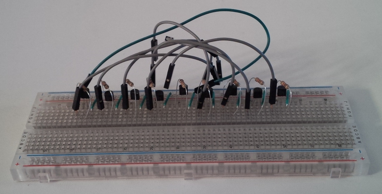
At first, I thought of just using a simple resistor-transistor logic controlled by GPIOs. I tested it out just to see how easy it would be and it worked pretty well.
However, some quick research on the Internet suggested that being electrically isolated was a better idea. Enter the optocoupler. For those unfamiliar with an optocoupler, it’s basically an LED and photosensitive transistor in a package. Any short on the inputs or outputs would blow the optocoupler without leaking any current into the other circuit. This protects the GPIO controller from the motherboard.
The alternative here was to use a relay, either mechanical or solid state. The former seemed too loud, bulky, and may eventually wear out. Though it would likely take a long time to wear out with such a low voltage being used. Regardless, I don’t like the idea of things wearing out if they don’t have to. The latter solid state relay, after looking into them more, is essentially just an optocoupler anyway.
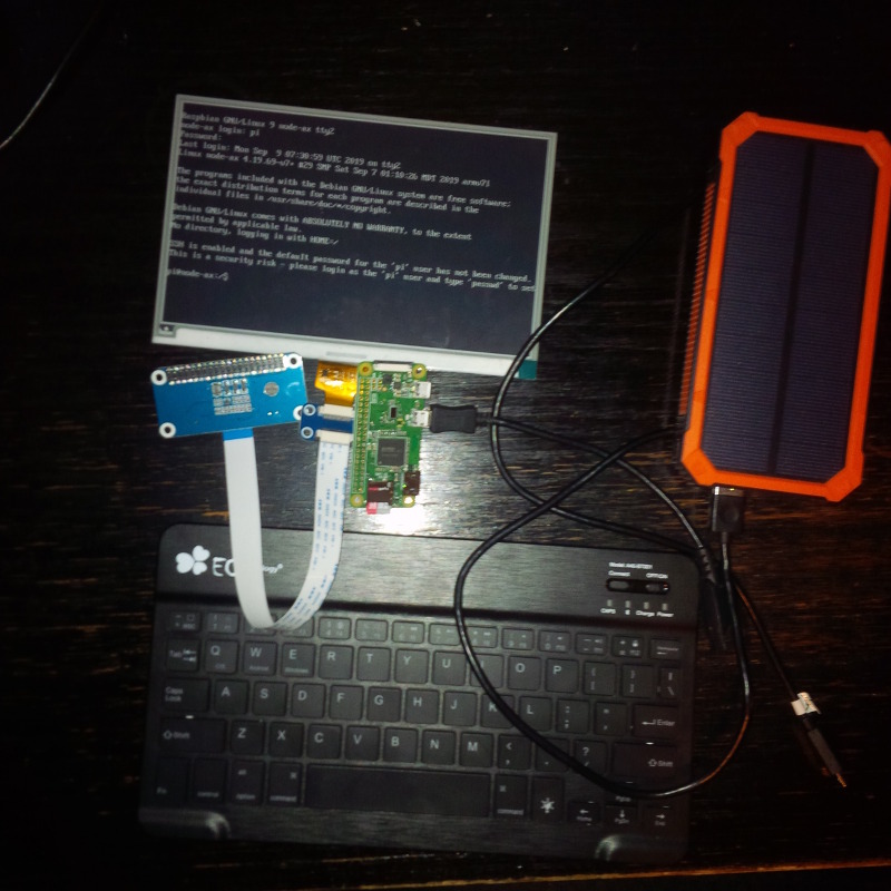
As a GPIO controller, I chose the ubiquitous Raspberry Pi (RPi) 3. It’s high-level enough to provide SSH access, but can still control GPIOs. It’s also readily available, easy to replace or scale, and provides ample GPIOs out of the box. As is, it’s capable of [controlling 25 GPIOs](https://pinout.xyz/#]. All this for $50. Still amazes me.
Because the optocoupler behaves like a transistor/LED, resistors are needed to keep any misconfiguration on the controller side from sinking too much current through the GPIOs. Without current limiting, the RPi could potentially be configured to sink too much current into ground and potentially fry it. A resistor was added to the input of the optocoupler to limit the current. The resistor size was selected based on the maximum current specification for the GPIOs on the RPi.
Prototyping the Device
After running this GPIO switch design through testing, it became apparent that the solution would also need some kind of reliable way of determining if the system was actually on. Reading the power LED pins from the motherboard became an immediate solution. Since the optocoupler is essentially just an LED anyway, why not just put it in reverse? Unsurprisingly, testing showed a positive result. However, this would mean that the number of motherboard ports per RPi would be halved, as one GPIO would be used as an output to drive the switch and one would be used as an input to read the LED power pin. This feedback is essential for operation so I decided to proceed with it.
Similarly with the power switch portion, the power LED reading was protected with resistors. One to limit current from VCC and one to limit current from the GPIO. This lead to the basic design:
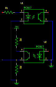
Here you can see the GPIO input is connected to the collector of the photosensitive transistor in the optocoupler (pin 3 of U2). If the optocoupler is enabled, it will open the voltage from VCC and create a voltage potential to be detected by the RPi as a 1.
It’s also worth noting that no resistors are needed on the motherboard side. Physical switches and LEDs are normally connect directly to the motherboard so I can rely on this already being take of.
Repeating this design twelve more times for the available GPIOs and wiring it up to headers, resulted in this schematic:
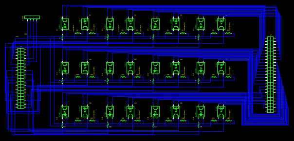
I also wired up VCC, ground, and the leftover serial TX/RX lines to a separate 4-pin header. They seemed like the best choice for the odd number left over from the switch and LED pairs. The VCC and ground pins are nice for testing as well.
The schematics were created in gEDA (IE. gschem). I chose to try out gEDA because tutorials online showed decent results. I also like to use open source software as much as possible. With the schematics created, next was to do the PCB layout and routing.
I chose Seeed Studio as my first PCB manufacturer. People on other forums were recommending them and their prices were more than affordable. It’s important to select a manufacturer before starting the PCB layout because the manufacturer limitations have a significant impact on the layout process. For example, minimum copper spacing determines how closely traces can be packed together. Fortunately, given the simplicity of the design and the ample room on the first iteration, it was fairly easy to place the components and let the auto-router route the ratnest given the supplied design restrictions.
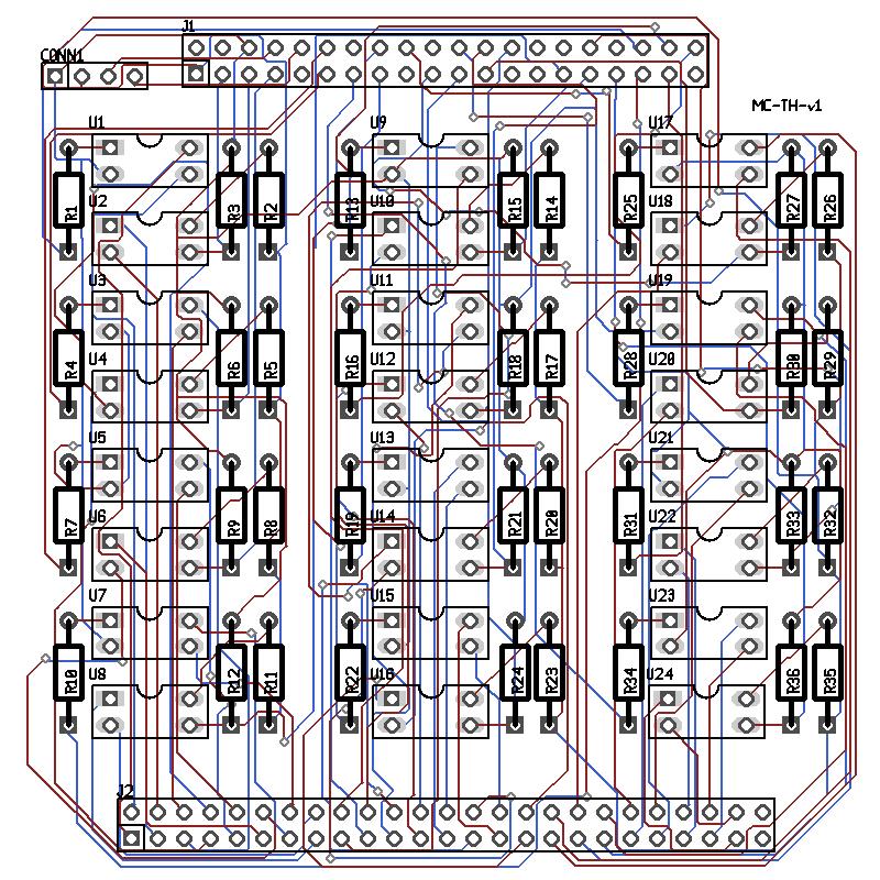
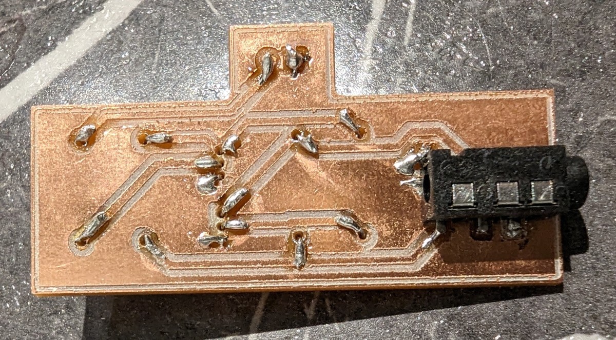
The results were pretty good. I assembled and tested the board. Unfortunately, I found two issues. First, it seems when I initially created the PCB, I used an “auto-optimize” function that disconnected the traces from the optocouplers. I’m not sure if I did something wrong or whether there’s a bug in the program, but the netlist checker didn’t seem to complain about the disconnected net. This is either because the bottom side pad is within range of the top trace or it’s simply a bug.
The second was my initial schematics (not shown above), used the same valued resistors on each power/LED pair but for some reason, the voltage for the power LED part on the first and second port was insufficient to be detected by the RPi as 0. All the other ports worked as intended. This meant the power status for the first two ports remained on no matter what I did. To fix this, I simply wired the design back up to a breadboard to find a resistor that would work. I then replaced the resistor on the initial board and all was well.
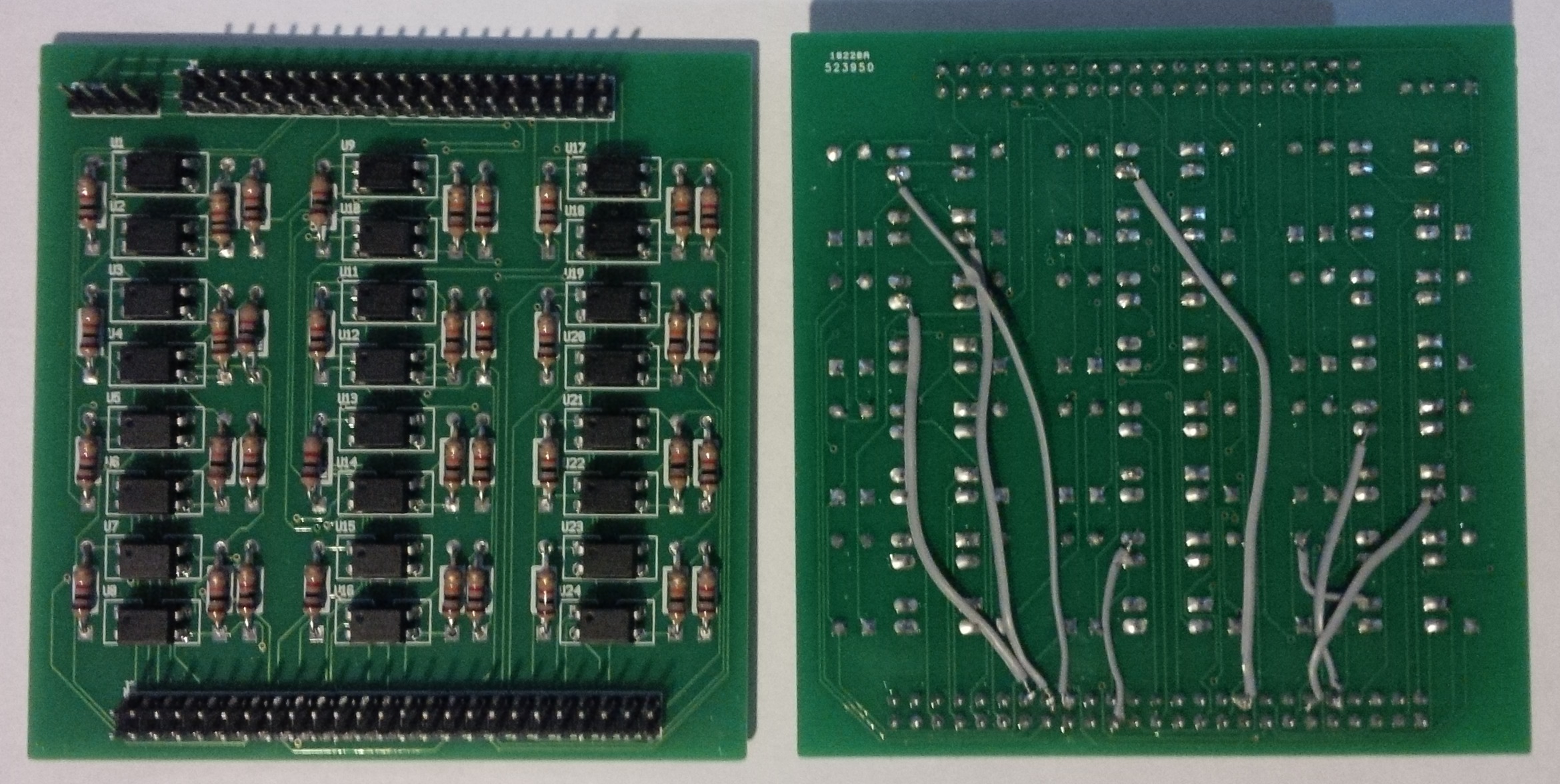
As you can see, the fly wires on the board were unacceptable for long-term use, so I corrected the traces and resubmitted.
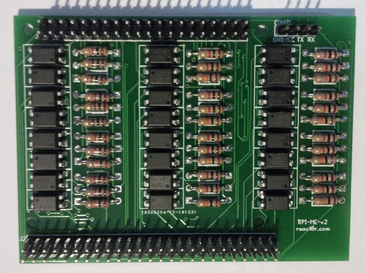
I called the device moboctrl or motherboard controller.
Device deployment
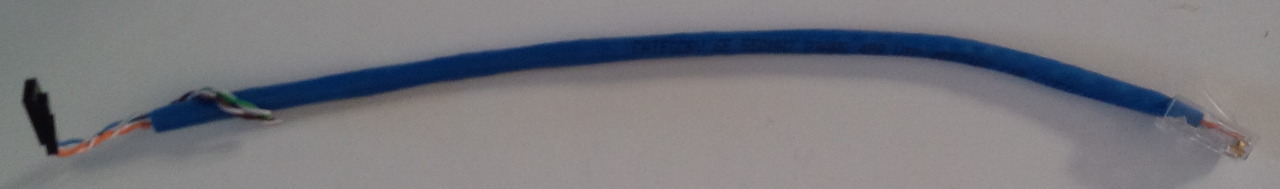
With this new moboctrl board created, there was also the issue of wiring it all up to all the controlled systems. The question was how to wire all this up to motherboards at scale? Initially, I used Cat6 cable pair scraps stuffed into jumper wires. This was simple to do but terribly fragile, never mind at scale.
My second iteration was to use Cat6 crimped with female Molex pins on one end and male RJ46 (aka crystals) on the other. Then those were coupled and plugged into a patch panel. Pre-made cables were used for any significant length. This was better for longer distances but the crimped Molex took way too long to do and still randomly came off. Crimping RJ45 is no party either. If I recall, this took about an hour per port, which is abysmal.
Getting away from that, my current iteration uses female RJ45 (aka keystones) instead, with pre-made 2-pin header cables that I could just cut and punch into the keystones. I called these ethernet header adapters. I also decided to give up gigabit speeds and made use of the second Cat6 twisted pair to serve the power and LED ports. This loss of bandwidth is fine for altcoin mining, but unsure of the impact to ML, since my ML project is currently on hold. It does create a cleaner solution as there are fewer cables.
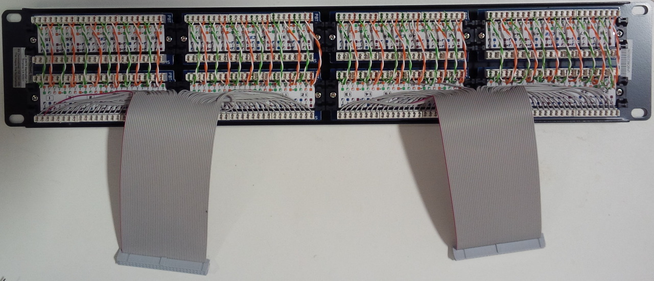
To accomplish this, I used a 48-port patch panel controlled by two motherboard controllers attached to one RPi each. The top ports on the patch panel are the incoming cables from each system. The orange and green pair (used for 100 Mbit ethernet) are passed through to the corresponding bottom ports. The bottom ports then go to a normal switch. The remaining blue and brown pairs have a 50-pin ribbon cable punched into it. The ribbon cables then attach to the moboctrl on the RPi.
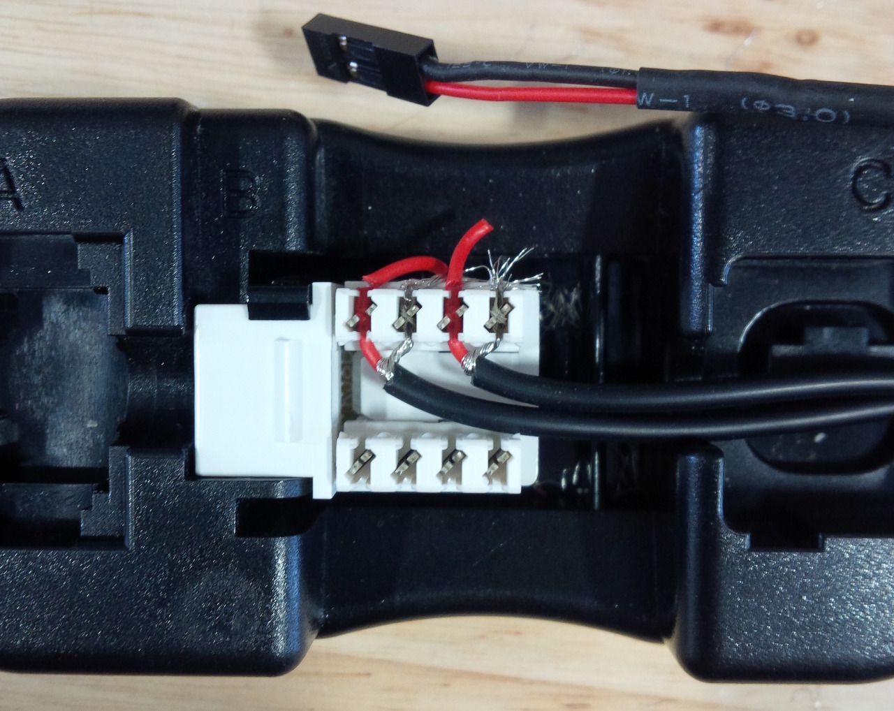
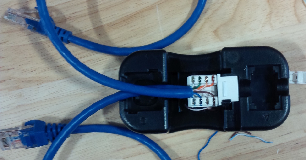
On the motherboard end, I punched the 2-pin header cables into the keystone for the adapter and created an ethernet economizer punched with two ends of a pre-made Cat 5e cable to split the pairs for the motherboard. The adapter took about 3 minutes and the economizer took about 5 minutes each, which included testing with the adapter.
In this setup, the RPi is closer to the network switch, which ends up being about 18 meters away from the motherboard it controls. Despite the computation verifying it would work, I was still skeptical the length wouldn’t cause problems. Fortunately, it worked flawlessly except for a minor issue with one of the pre-made cables having a small piece of plastic that created a disconnection if the wire was ever just so. I scraped the plastic away and all was fine.
Software
With everything hooked up, I used the pre-installed GPIO package in Python to drive the GPIOs. I created a small script to pulse the power switch and simulate a press. The script also read the inputs to return a motherboard power state value.
With that written, I can then use SSH to control the systems remotely from within the network with something
ssh pi@pi './moboctrl.py -r 0'which will reset (-r) the system with a long pulse to force it off, then short pulse to turn the system back on.
Wiring Alternative
One alternative to the wiring is to deploy RPis closer to the systems. Thus, freeing up the blue and brown twisted pairs on the network for gigabit speeds. The idea here would be to enclose an RPi and moboctrl into a device box. The motherboard controllers would be attached to a ribbon cable that’s punched into 24 keystones for the device box. The device box could then be mounted near by. Unfortunately, the highest port device box plates I found were 12 port.
Also, the initial version of the moboctrl has no mounting holes. With no way of mounting the board, it would be rattling around in the device box unless I got creative with a mounting solution. I decided to add mounting holes and to make it more RPi-sized in case there were other applications where size was important.
Fortunately, I was able to accomplish those goals with the auto-router in gEDA. Though, this solution was a little more involved. First, I needed to flip every second optocoupler to reduce the number of times each ratnest air wire crossed. This was done because each time an air wire crossed, a board via is needed to route the trace. However, vias are typically reduced for bunch of reasons such as cost.
Second, I needed to use a different printer as I learned Seeed’s higher-resolution limits are more expensive. You’d only noticed this once you checkout, which is annoying. Thankfully, another printer (JLCPCB) was able to do it at a lower cost, so I gave them a try. One thing they noted was that my “holes” were only pads with no holes. Turns out gEDA will break up plated and unplated holes into different files. These files needed to be merged into a single drill file. Both files are in the same XNC or XNC-like format so merging them was more or less a copy and paste.
Closing Remarks
With all the wiring that’s ripe with error, I’m surprised at how well it all worked. The RPis are very stable, and I’ve never had any inconsistencies with the motherboard controllers. I’ve been running this solution for about a year with no issues.
If anyone else thinks this might be useful, feel free to reach out. If there’s enough interest, I’m open to getting these mass produced and/or releasing the design files and scripts. Though, I think there’s still quite a bit of refinement that could be done.